Actuators with internal track roller guidance system
Features
Linear actuators MLFI..-ZR and MLFI..-3ZR comprise:
- a carriage available in various lengths
- an internal track roller guidance system
- a support rail unit with internal running shafts for the carriage
- a toothed belt drive
- two return units (in the case of sizes MLFI25 and MLFI34, the return unit is integrated).
Actuators MLFI..-(3)ZR are driven linear units of a lightweight construction. Their area of application is characterised by low to moderate accuracy requirements, long travel distances with consistently low displacement resistance and low to moderate loads and moments. They facilitate high travel velocities and are resistant to contamination. Their smooth running characteristics are ensured by two pairs of large sized, maintenance-free track rollers.
The carriages have three or four track rollers and run on two parallel internal shafts inserted in the support rail. The track rollers on a carriage are set clearance-free. A track roller is a double row angular contact ball bearing with a heavy section, profiled outer ring.
Drive is provided by a preloaded, wear-resistant toothed belt that is guided and wrapped at the ends by external or internal return units.
Accessories available for the actuators include fasteners and connectors, couplings and coupling housings and electric drive components such as motors, motor/gearbox units and controllers.
The track rollers are mounted internally and are completely covered by the toothed belt guided in the guideway. This design with internal profiled track rollers gives a wide range of actuator cross-sections, from small rectangular or square cross-sections up to large rectangular cross-sections.
Designs
Linear actuators of series MLFI..-(3)ZR are available in various designs, see table. The possible designs and combinations vary according to the size and actuator type.
Available designs
Suffix | Description | Design |
|---|---|---|
‒ | One driven carriage | Basic design |
LN | Low Noise design, only for MLFI50..-C-ZR | Standard |
FA517 | Multi-piece support rail | Standard |
RB | Corrosion-resistant design | Special design |
W2 | Second, driven carriage | Standard |
N | Two fixing slots in carriage | Standard |
Special designs
Special designs are available by agreement. Examples of these are linear actuators:
- with more than two driven carriages
- with two (or more) driven carriages of different length
- with reinforced or antistatic toothed belt or toothed belt of high temperature design
- without drive
- with T-strips inserted in the T-slots of the support rail
- with extended carriages
- with a compressed air connection in the support rail or in the return units
- with a drive stud of special dimensions
- with special machining.
Combinations
Possible combinations are:
- linear actuator with two driven carriages and a multi-piece support rail
- linear actuator in the Low-Noise design and with two driven carriages and a multi-piece support rail.
Carriage
The carriage has a saddle plate made from anodised aluminium. It is guided by three or four profiled track rollers of series LFR. The carriage is set clearance-free by means of eccentric bolts in the track rollers.
The carriage contains integral tensioners on both sides for the toothed belt. The available carriage lengths are dependent on the actuator sizes, see table and ➤ Figure.
Lengths of carriages
Series | Carriage length | Suffix |
|---|---|---|
mm | ||
MLFI20..-ZR | 130 | 130 |
250 | 250 | |
MLFI25..-ZR | 130 | 130 |
250 | 250 | |
500 | 500 | |
MLFI34..-ZR | 260 | 260 |
MLFI50..-C-ZR | 250 | 250 |
500 | 500 | |
MLFI140..-3ZR | 240 | 240 |
500 | 500 | |
MLFI200..-3ZR | 365 | 365 |
500 | 500 |
Carriage

Longer carriage or second carriage
The carriages of linear actuators are available in various lengths. Longer carriages allow support of higher moment loads.
Optionally, a second driven carriage can be fitted.
Movable or stationary carriage
A movable carriage is mounted and used as follows, ➤ Figure:
- where a long stroke length or total length is required
- predominantly for horizontal mounting.
A stationary carriage is mounted and used as follows, ➤ Figure:
- where a short stroke length is required
- predominantly for vertical mounting.
Movable or stationary carriage


Lubrication
The carriage is fitted with lubrication nipple units. These are used to lubricate the guidance shafts of the guideway. The track rollers are greased and do not require lubrication.
Location
For location on the adjacent construction, the carriages have two or more T-slots to which the structure to be moved is fixed. Exceptions: In the case of MLFI20..-ZR and MLFI34..-ZR, the carriage has threaded holes.
Support rail unit
The support rail unit is a composite unit. It comprises a carrier profile made from anodised aluminium with two rolled-in high precision running shafts to grade h6 made from high alloy steel.
The running shafts are hardened and ground. Since the support rail has very high bending rigidity, it can be used to span large gaps.
Guideway length
The maximum guideway length is dependent on the size.
Longer lengths can be achieved starting from size MLFI50 by combining several support rail segments. The support rail segments are connected at their butt joints by means of two laterally screw mounted and dowelled aluminium plates.
One return unit and the carriage are premounted on the first support rail segment. The other support rail segments with the screw mounted and dowelled aluminium plates, the second return unit and the toothed belt are supplied in addition and must be fitted by the customer, see ➤ section.
T-slots
Support rails and carriages (with the exception of MFLI20 and MLFI34) have T-slots for standardised T-nuts. These are used in order to fix the actuators to the adjacent construction, link.
Return unit
The return units of the linear actuator MLFI20 comprise a support rail segment that has been adapted, ➤ Figure. The return units of the linear actuators MLFI25 and MLFI34 are integrated in the support rail. The return units of the linear actuators MLFI50, MLFI140 and MLFI200 are incorporated in a housing made from profiled anodised aluminium.
In all return units, the shafts are supported on both sides by ball bearings lubricated for life. The toothed belt is wrapped by means of a gear mounted on the shaft.
Return unit of MLFI20..-ZR

Return unit of MLFI25..-ZR, MLFI34..-ZR

Return unit of MLFI..-3ZR

Toothed belt
A reinforced toothed belt is fitted that allows the transmission of high tensile forces with a long rating life. Tensioning of the belt is carried out by means of the tensioning unit in the carriage.
Drive
The actuators are available without a drive shaft as well as with a drive shaft on the left side, right side or passing through the unit, see table. Possible combinations and drive variants, see also ➤ section.
Suffixes
Drive variants | Suffix |
|---|---|
Drive shaft on left side | AL |
Drive shaft on right side | AR |
No drive shaft | OZ |
Drive shaft on both sides (left and right) | RL |
Drive variants


for T-nuts and T-bolts
on single-piece support rails ·

(carriage side with eccentric bolts) ·

Drive elements
For actuators, Schaeffler also supplies components such as couplings, coupling housings and planetary gearboxes as well as servo motors and servo controllers, ➤ Figure.
Linear actuator with drive elements


Proven drive combinations
For vertical and horizontal applications, the necessary drive components can be combined as a function of the mass to be moved, the acceleration and the travel velocity of the carriages.
Mechanical accessories
A large number of accessories are available for linear actuators with internal track roller guidance system. The allocation of accessories is valid if the data match the Technical principles and the Design and safety guidelines, link.
Allocation
Linear actuator | MLFI..-ZR | MLFI..-3ZR | |||||
|---|---|---|---|---|---|---|---|
Size | 20 | 25 | 34 | 50 | 140 | 200 | |
Fixing brackets | |||||||
WKL-48×48×35 | ‒ | ‒ | ‒ | ‒ |
| | |
WKL-65×65×35 | ‒ | ‒ | ‒ | ‒ | | ‒ | |
WKL-65×65×30-N | ‒ | ‒ | | | | | |
WKL-65×65×35-N | ‒ | ‒ | ‒ | | | ‒ | |
WKL-90×90×35-N | ‒ | ‒ | ‒ | | | ‒ | |
WKL-98×98×35 | ‒ | ‒ | ‒ | ‒ | ‒ | | |
Clamping lugs | |||||||
SPPR-12×20 | | ‒ | ‒ | ‒ | ‒ | ‒ | |
SPPR-13,5×20 | ‒ | ‒ | ‒ | | ‒ | ‒ | |
SPPR-22×20 | ‒ | ‒ | ‒ | ‒ | | ‒ | |
SPPR-24×20 | ‒ | | | ‒ | ‒ | ‒ | |
SPPR-23×30 | ‒ | ‒ | ‒ | | ‒ | ‒ | |
SPPR-26×30 | ‒ | ‒ | ‒ | ‒ | ‒ | | |
SPPR-28×30 | ‒ | ‒ | ‒ | ‒ | | | |
T-nuts | |||||||
| MU-DIN 508 M4×5 | ‒ |  | | ‒ |  | ‒ |
MU-M3×5 | ‒ | | | ‒ | | ‒ | |
MU-DIN 508 M6×8 | ‒ | ‒ | ‒ | |  | | |
MU-M4×8 | ‒ | ‒ | ‒ | | | | |
MU-DIN 508 M8×10 | ‒ | ‒ | ‒ | ‒ | ‒ |  | |
MU-M6×10 | ‒ | ‒ | ‒ | ‒ | ‒ | | |
T-nuts made from corrosion-resistant steel | |||||||
MU-DIN 508 M4×5-RB | ‒ | | | ‒ | | ‒ | |
MU-DIN 508 M6×8-RB | ‒ | ‒ | ‒ | | | | |
MU-DIN 508 M8×10-RB | ‒ | ‒ | ‒ | ‒ | ‒ | | |
 | Suitable. |
 | Only for the lowest lateral T-slot in the support rail. |
 | Only with M5 screws, only in the lateral T-slots in the support rail. |
 | For T-slots in the support rail. |
 | For T-slots in the support rail and carriage. |
 | For 5 mm wide T-slots in the support rail. |
 | For 8 mm wide T-slots in the support rail and carriage. |
 | For 10 mm wide T-slots in the support rail. |
Allocation
Linear actuator | MLFI..-ZR, MLFI..-3ZR | ||||||
|---|---|---|---|---|---|---|---|
Size | 20 | 25 | 34 | 50 | 140 | 200 | |
T-bolts | |||||||
| SHR DIN 787-M5×5×25 | | | | ‒ | | ‒ |
SHR DIN 787-M8×8×32 | ‒ | ‒ | ‒ | | | | |
SHR DIN 787-M10×10×40 | ‒ | ‒ | ‒ | ‒ | ‒ | | |
Rotatable T-nuts | |||||||
| MU-M3×5-RHOMBUS | | | | ‒ | | ‒ |
MU-M4×8-RHOMBUS | ‒ | ‒ | ‒ | | | | |
MU-M6×8-RHOMBUS | ‒ | ‒ | ‒ | | | | |
MU-M8×10-RHOMBUS | ‒ | ‒ | ‒ | ‒ | ‒ | | |
Positionable T-nuts | |||||||
MU-M4×5-POS | | | | ‒ | | ‒ | |
MU-M5×5-POS | | | | ‒ | | ‒ | |
MU-M4×8-POS | ‒ | ‒ | ‒ | | | | |
MU-M5×8-POS | ‒ | ‒ | ‒ | | | | |
MU-M6×8-POS | ‒ | ‒ | ‒ | | | | |
MU-M8×8-POS | ‒ | ‒ | ‒ | | | | |
Hexagon nuts | |||||||
MU-ISO 4032 M5 | | | | ‒ | | ‒ | |
MU-ISO 4032 M8 | ‒ | ‒ | ‒ | | | | |
MU-ISO 4032 M10 | ‒ | ‒ | ‒ | ‒ | ‒ | | |
T-strips | |||||||
LEIS-M4/5-T-NUT-SB-ST | | | | ‒ | | ‒ | |
LEIS-M4/5-T-NUT-HR-ALU |  | | | ‒ | | ‒ | |
LEIS-M6/8-T-NUT-SB-ST | ‒ | ‒ | ‒ | | | | |
LEIS-M8/8-T-NUT-SB-ST | ‒ | ‒ | ‒ | | | | |
LEIS-M6/8-T-NUT-HR-ST | ‒ | ‒ | ‒ | | | | |
LEIS-M6/8-T-NUT-HR-ALU | ‒ | ‒ | ‒ | | | | |
LEIS-M4/5-T-NUT-ST | ‒ | | | | | | |
LEIS-M6/8-T-NUT-ST | ‒ | ‒ | ‒ | | | | |
LEIS-M8/10-T-NUT-ST | ‒ | ‒ | ‒ | ‒ | ‒ | | |
Connector sets (parallel connectors) | |||||||
VBS-PVB8 | ‒ | ‒ | ‒ | | | | |
VBS-PVB10 | ‒ | ‒ | ‒ | ‒ | ‒ | | |
VBS-PVB8/10 | ‒ | ‒ | ‒ | | | | |
Slot closing strips | |||||||
NAD-5×5,7 | | | | ‒ | | ‒ | |
NAD-8×4,5 | ‒ | ‒ | ‒ | | | | |
NAD-8×11,5 | ‒ | ‒ | ‒ | | | | |
NAD-10×6,5 | ‒ | ‒ | ‒ | ‒ | ‒ | | |
| Suitable. |
| For T-slots in the support rail. |
| For T-slots in the support rail and carriage. |
| For 5 mm wide T-slots in the support rail. |
| For 8 mm wide T-slots in the support rail and carriage. |
| For 10 mm wide T-slots in the support rail. |
 | These must be inserted in the T-slots at the manufacturing plant. |
Design and safety guidelines
Load carrying capacity and
load safety factor
The load carrying capacities and load safety factors to be observed differ as a function of the mounting position.
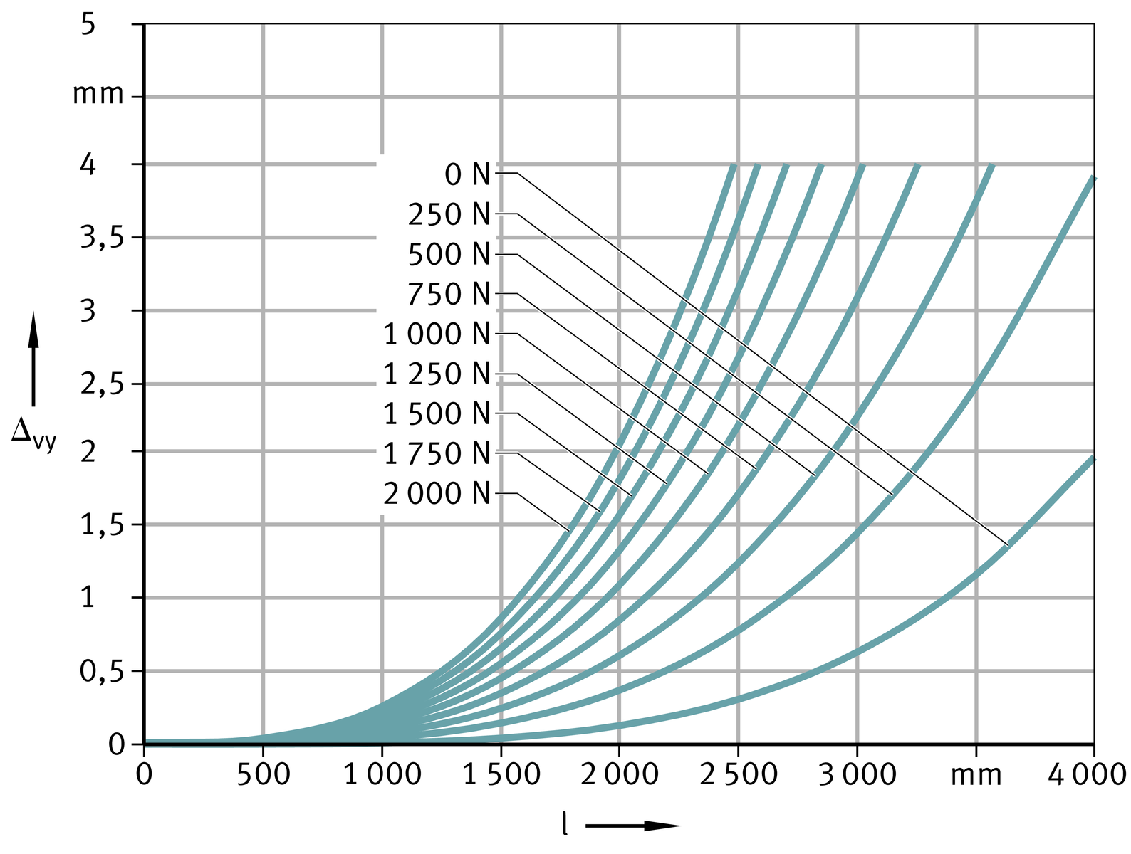
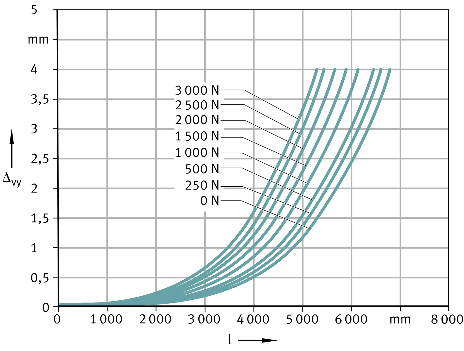
Deflection
The deflection of linear actuators is essentially dependent on the support spacing, the rigidity of the support rail, the adjacent construction and the bearing arrangement. As the rigidity of these components increases, the deflection of the actuators is reduced.
Diagrams
The diagram values are determined for a bearing arrangement or clamping which is in theory infinitely rigid and are subdivided into locating/non-locating and locating/locating bearing arrangements, starting ➤ Figure.
The deflection of the support rail is valid under the following conditions:
- support rail unit comprising carrier profile and guidance shafts
- support spacings up to 8 000 mm
- introduction of the load at the centre of the carriage if this is at the centre point between the bearing points.
ATTENTION
The diagrams represent guide values only for the deflection of the support rail, starting ➤ Figure. The effect of deflection on the rating life of the guidance system is not taken into consideration.
It is not possible to provide deflection diagrams for actuators with two carriages since there will be different spacings between the carriages. In such cases, please consult the Schaeffler Group Industrial engineering service.
Deflection about the z axis

Deflection about the z axis

Deflection about the y axis

Deflection about the y axis

Deflection about the z axis

Deflection about the z axis

Deflection about the y axis

Deflection about the y axis

Deflection about the z axis

Deflection about the z axis

Deflection about the y axis

Deflection about the y axis

Deflection about the z axis
Deflection about the z axis

Deflection about the y axis

Deflection about the y axis

Deflection about the z axis

Deflection about the z axis

Deflection about the y axis

Deflection about the y axis

Deflection about the z axis

Deflection about the z axis

Deflection about the y axis

Deflection about the y axis

Deflection about the z axis

Deflection about the z axis
Deflection about the y axis

Deflection about the y axis

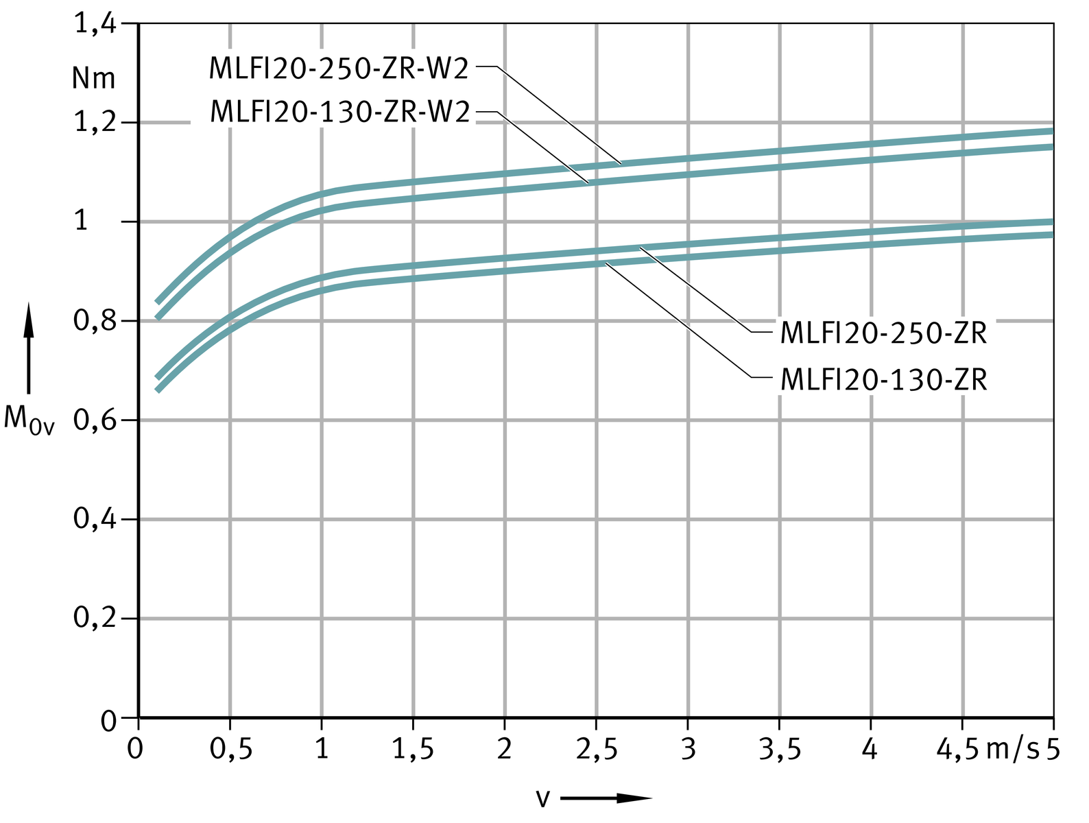
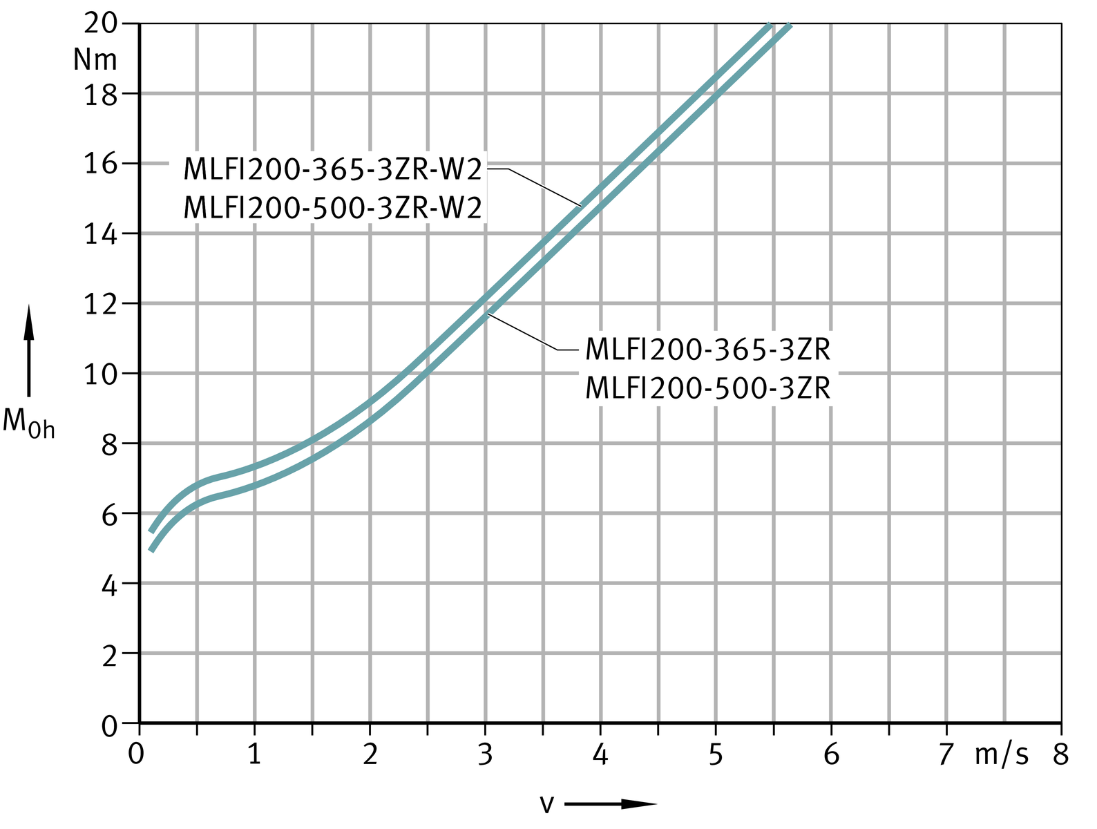
Idling drive torque
The idling drive torque M0 of linear actuators is calculated for a constant velocity and for a horizontal (M0h) or vertical (M0v) mounting position, starting ➤ Figure. The idling drive torque increases with increasing travel velocity. The data in the diagrams are maximum values.
Idling drive torque
Horizontal mounting position

Idling drive torque
Vertical mounting position
Idling drive torque
Horizontal mounting position

Idling drive torque
Vertical mounting position

Idling drive torque
Horizontal mounting position

Idling drive torque
Vertical mounting position

Idling drive torque
Horizontal mounting position

Idling drive torque
Vertical mounting position

Idling drive torque
Horizontal mounting position

Idling drive torque
Vertical mounting position

Idling drive torque
Horizontal mounting position
Idling drive torque
Vertical mounting position

Length calculation of actuators
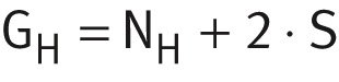
The length calculation of actuators is based on the required effective stroke length NH. The effective stroke length NH must be increased by the addition of safety spacing values on both sides of the travel distance.
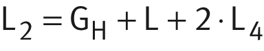
The total length Ltot of the actuator is determined from the total length L2, the lengths of the return units L4 on both sides and the carriage length L or the carriage length L1. If two carriages are present, both carriage lengths and the spacing Lx1 between the carriages must be taken into consideration.
Parameters for length calculation
| GH | mm | Total stroke length |
| NH | mm | Effective stroke length |
| S | mm | Safety spacing, for minimum values see table |
| L | mm | Length of carriage |
| L1 | mm | Total length of carriage |
| L2 | mm | Length of support rail |
| L4 | mm | Length of return unit |
| L6 | mm | Length of wiper brushes |
| L21 | mm | Length of cover plate |
| Ltot | mm | Total length of actuator |
| Lx1 | mm | Spacing between two carriages. |
Total stroke length
The total stroke length GH is determined from the required effective stroke length and the safety spacings.
Single-piece and multi-piece support rails
The maximum length of single-piece support rails, the maximum length of a support rail and the safety spacings S are dependent on size, see table. Actuators of size MLFI50 and above can be supplied in a multi-piece design, see table. The shortest segment length for MLFI50 is 500 mm, while in the case of MLFI140 and MLFI200 it is 1 000 mm.
Safety spacing S, maximum single-piece support rail length L2
Actuator | Maximum support rail length L2 (FA517) | Maximum length of single‑piece support rails L2 | Support rail segment length | Safety spacing S |
|---|---|---|---|---|
mm | mm | mm | ||
MLFI20..-ZR | 2 000 | 2 000 | 1 | 40 |
MLFI25..-ZR | 4 000 | 4 000 | 1 | |
MLFI34..-ZR | 6 000 | 6 000 | 1 | 80 |
MLFI50..-C-ZR | 24 000 | 8 000 | 3 | 85 |
MLFI140..-3ZR | 24 000 | 8 000 | 3 | |
MLFI200..-3ZR | 24 000 | 8 000 | 3 |
Spacing Lx1 between carriages
The minimum spacing Lx1 between two carriages is 50 mm for sizes MLFI20, MLFI25, MLFI34 and MLFI50. For sizes MLFI140 and MLFI200, the minimum spacing Lx1 is 100 mm.
Total length Ltot and support rail length L2
The following ➤ equtions are designed for one and two carriages. The parameters and their position can be found in ➤ Figure and ➤ Figure as well as in the table. If more than two carriages are present, please consult us.
Length parameters for one carriage

One carriage
Size: MLFI20

Total length Sizes: MLFI20

Length parameters for one carriage

One carriage
Size: MLFI25
One carriage
Size: MLFI34

Total length
Sizes: MLFI25, MLFI34

Length parameters for two carriages

Two carriages
Size: MLFI20

Total length Sizes: MLFI20
Length parameters for two carriages

Two carriages Size: MLFI25

Two carriages Size: MLFI34

Total length Sizes: MLFI25, MLFI34
Length parameters for one carriage

One carriage
Sizes: MLFI50, MLFI140, MLFI200

Total length
Sizes: MLFI50, MLFI140, MLFI200

Length parameters for two carriages

Two carriages
Sizes: MLFI50, MLFI140, MLFI200

Total length
Sizes: MLFI50, MLFI140, MLFI200
Length parameters
Designation | L | L1 | L4 | L6 | L21 | S |
|---|---|---|---|---|---|---|
mm | mm | mm | mm | mm | mm | |
MLFI20-130-ZR | 130 | ‒ | 76 | ‒ | 2 | 40 |
MLFI20-250-ZR | 250 | |||||
MLFI25-130-ZR-N | 130 | ‒ | 65 | ‒ | 2,5 | 40 |
MLFI25-250-ZR-N | 250 | |||||
MLFI25-500-ZR-N | 500 | |||||
MLFI34-260-ZR | 260 | 298 | 69 | ‒ | 1,3 | 85 |
MLFI50-250-C-ZR-N | 250 | 260 | 97 | 6 | ‒ | 85 |
MLFI50-250-C-LN-ZR-N | ||||||
MLFI50-500-C-ZR-N | 500 | 510 | 97 | 6 | ‒ | 85 |
MLFI50-500-C-LN-ZR-N | ||||||
MLFI140-240-3ZR-N | 240 | 282 | 80 | 6 | ‒ | 85 |
MLFI140-500-3ZR-N | 500 | 542 | ||||
MLFI200-365-3ZR-N | 365 | 405 | 115,5 | ‒ | 85 | |
MLFI200-500-3ZR-N | 500 | 540 |
Mass calculation
The total mass of an actuator is calculated from the mass of the actuator without a carriage, the carriage and the special design: multi-piece support rail (FA517) and second carriage (W2), ➤ Figure. Insert the values from the table in the following ➤ equation. The values mLAW and mBOL are mandatory.

Basic and additional designs

Values for mass calculation
Designation | Mass | |
|---|---|---|
Carriage | Actuator without carriage | |
mLAW | mBOL | |
≈kg | ≈kg | |
MLFI20-130-ZR | 0,25 | (Ltot – 152) · 0,0022 + 0,72 |
MLFI20-250-ZR | 0,38 | |
MLFI25-130-ZR..-N | 0,41 | (Ltot – 130) · 0,003 + 0,76 |
MLFI25-250-ZR..-N | 1,2 | |
MLFI25-500-ZR..-N | 1,7 | |
MLFI34-260-ZR | 1,4 | (Ltot · 0,007) + 1,4 |
MLFI50-250-C-ZR..-N | 2,27 | (Ltot – 194) · 0,0112 + 4,7 |
MLFI50-500-C-ZR..-N | 3,22 | |
MLFI140-240-3ZR..-N | 5,5 | (Ltot – 160) · 0,0154 + 7,33 |
MLFI140-500-3ZR..-N | 8,87 | |
MLFI200-365-3ZR..-N | 13,3 | (Ltot – 231) · 0,0309 + 18,6 |
MLFI200-500-3ZR..-N | 16,5 | |
Values for mass calculation
Designation | Mass Design | ||
|---|---|---|---|
m1 | m3 | ||
FA517.1 | FA517.2 | W2 | |
≈kg | ≈kg | ≈kg | |
MLFI20-130-ZR | ‒ | ‒ | 0,25 |
MLFI20-250-ZR | ‒ | ‒ | 0,38 |
MLFI25-130-ZR..-N | ‒ | ‒ | 0,41 |
MLFI25-250-ZR..-N | ‒ | ‒ | 1,2 |
MLFI25-500-ZR..-N | ‒ | ‒ | 1,7 |
MLFI34-260-ZR | ‒ | ‒ | 1,4 |
MLFI50-250-C-ZR..-N | 1,4 | 2,78 | 2,27 |
MLFI50-500-C-ZR..-N | 3,32 | ||
MLFI140-240-3ZR..-N | 1,84 | 3,69 | 5,5 |
MLFI140-500-3ZR..-N | 8,87 | ||
MLFI200-365-3ZR..-N | 3,68 | 13,3 | |
MLFI200-500-3ZR..-N | 16,5 | ||
Lubrication
The guidance system in linear actuators must be lubricated during operation.
The profiled track rollers sealed on both sides are greased with a high quality lithium soap grease and the track roller sizes used are classified as lubricated for life.
The bearing arrangement of the toothed belt return units is maintenance-free.
Lubrication of the guideway
The raceways are lubricated by means of lubrication and wiper units containing oil-soaked felt inserts. These inserts are supplied from the factory already soaked with oil (H1 authorisation for the food industry).
For relubrication of the guideway raceways, oils of viscosity 460 mm2/s are recommended.
ATTENTION
The lubrication and wiper units are integrated in the MLFI carriage and must be supplied with oil via lubrication nipples.
Relubrication intervals
The relubrication intervals are essentially dependent on the following factors:
- the travel velocity of the carriage
- the load
- the operating temperature
- the stroke length
- the environmental conditions and environmental influences
- the mounting position.
Lubrication intervals
The lubrication intervals are dependent on the environmental influences. The cleaner the environment, the smaller the quantity of lubricant consumed. The time and quantity can only be determined precisely under operating conditions since it is not possible to determine all the influences by calculation. An observation period of adequate length must be allowed.
ATTENTION
Fretting corrosion is a consequence of lubricant starvation and is visible as a reddish discolouration of the opposing raceway or the outer ring of the track roller. Lubricant starvation can lead to permanent damage to the system and therefore to its failure. It must be ensured that the lubrication intervals are reduced accordingly in order to prevent fretting corrosion.
Relubrication quantities
Relubrication should be carried out wherever possible with several partial quantities at various times instead of the complete quantity at the time of the relubrication interval. Grease quantities, see table.
Grease quantities
Linear actuator | Relubrication quantity per lubrication nipple and per end face |
|---|---|
≈g | |
MLFI20-130-ZR MLFI20-250-ZR | 1 to 2 |
MLFI25-130-ZR..-N MLFI25-250-ZR..-N MLFI25-500-ZR..-N | 2 to 3 |
MLFI34-260-ZR | 2 to 3 |
MLFI50-250-C-ZR..-N MLFI50-500-C-ZR..-N | 2 to 3 |
MLFI140-240-3ZR..-N MLFI140-500-3ZR..-N | 2 to 3 |
MLFI200-365-3ZR..-N MLFI200-500-3ZR..-N | 4 to 5 |
MLFI50-250-C-LN-ZR..-N MLFI50-500-C-LN-ZR..-N | 2 to 3 |
Relubrication procedure
Relubrication should be carried out whilst the carriage is moving and warm from operation over a minimum stroke length corresponding to one carriage length.
During lubrication, it must be ensured that the grease gun, grease, lubrication nipple and the environment of the lubrication nipple are clean.
Lubrication nipples for relubrication
The running shafts in the actuators are relubricated via lubrication devices in the carriage. Actuators of sizes 20 und 34 have drive fit lubrication nipples, ➤ Figure. Actuators of size 25 have access holes closed off by grub screws. Larger actuators have countersunk funnel type lubrication nipples.
Lubrication nipple and screw plug

Grub screw M2,5 DIN 913 ·
For relubrication, the carriage in MLFI50..-C-ZR, MLFI140..-3ZR or MLFI200..-3ZR can be connected to a semi-automatic or fully automatic central lubrication system. In this case, the funnel type lubrication nipples must be unscrewed and replaced by screw-in connectors M6×1. The central lubrication system is connected by means of pipes or hoses.
Relubrication points
The felt lubrication inserts in the lubrication and wiper units fitted are reoiled via drive fit lubrication nipples NIP A1 or via funnel type lubrication nipples to DIN 3405-A M6. Lubrication can be carried out from both end faces of the carriage, see ➤ Figure and table.
Lubrication points

Lubrication points on short carriage

Lubrication points

ATTENTION
During lubrication of linear actuators, all lubrication points on one longitudinal side of a carriage must always be provided with lubricant.
Lubrication points

Position of relubrication points
Designation | Mounting dimensions | |||||
|---|---|---|---|---|---|---|
l57 | h56 | l56 | S56 | t56 | G56 | |
mm | mm | mm | mm | mm | mm | |
MLFI20-130-ZR | 42,5 | 4,25 | 42,5 | ‒ | ‒ | ‒ |
MLFI20-250-ZR | 162,5 | |||||
MLFI25-130-ZR | ‒ | 11,5 | 7,5 | ‒ | ≦5 | M2,5 |
MLFI25-250-ZR | 145 | 45 | ||||
MLFI25-500-ZR | 395 | 55 | ||||
MLFI34-260-ZR | 99,5 | 10,5 | 80,3 | ‒ | ‒ | ‒ |
MLFI50-250-C..-ZR | ‒ | 13,5 | 125 | 15 | 5,6 | M6 |
MLFI50-500-C..-ZR | 297 | 101,5 | ||||
MLFI140-240-3ZR | ‒ | 20 | 120 | 15 | 3,5 | M6 |
MLFI140-500-3ZR | 250 | |||||
MLFI200-365-3ZR | ‒ | 28 | 182,5 | 15 | 3,5 | M6 |
MLFI200-500-3ZR | 250 | |||||
T-slots
The T-slots in the support rail and the carriage are designed for T-bolts according to DIN 787 and T-nuts according to DIN 508 (with the exception of T-slot size 4,5), ➤ Figure. T-nuts and T-bolts are inserted using filling slots in the support rail.
Sizes of T-slots in support rail and carriage

Dimensions of T-slots
Designation | Support rail | Carriage | ||
|---|---|---|---|---|
Lateral | Bottom | Top | Lateral | |
MLFI20..-ZR | | ‒ | ‒ | ‒ |
MLFI25..-ZR | | | | ‒ |
MLFI34..-ZR | | | ‒ | ‒ |
MLFI50..-C-ZR | | | | |
MLFI140..-3ZR | | | | |
| | | | |
MLFI200..-3ZR | | | | |
Filling openings
The filling openings, ➤ Figure and table, are always located on the opposing side to the drive.
Filling openings in support rail

Dimensions of filling openings in support rails
Designation | T-slot | Rectangular | Oval | |||
|---|---|---|---|---|---|---|
b | l | b | l | r | ||
MLFI20..-ZR | 5 | 10 | 12 | ‒ | ‒ | ‒ |
MLFI25..-ZR..-N | 5 | ‒ | ‒ | 12 | 15 | 6 |
MLFI34..-ZR | 5 | 15 | 12 | 5,2 | 5 | 2,5 |
MLFI50..-C-ZR..-N | 8 | 16 | 25 | ‒ | ‒ | ‒ |
MLFI140..-3ZR..-N | 5 | 12 | 25 | ‒ | ‒ | ‒ |
8 | 16 | |||||
MLFI200..-3ZR..-N | 8 | 16 | 25 | ‒ | ‒ | ‒ |
10 | 18,5 | |||||
Connectors for switching tags
Switching tags can be screw mounted to the carriage in order to activate switches in the adjacent construction. The position and size are dependent on the size, ➤ Figure, ➤ Figure and table.
Connectors for switching tags on the carriage

Connectors for switching tags on carriage of series MLFI50-C-ZR

Mounting dimensions for switching tags
Series | Mounting dimensions | ||||
|---|---|---|---|---|---|
Actuator | JL58 | l58 | h58 | G58 | t58 max |
mm | mm | mm | mm | mm | |
MLFI20-130-ZR | 20 | 5,5 | 5 | M3 | 7 |
MLFI20-250-ZR | |||||
MLFI25-130-ZR | 40 | 10 | 11,2 | M3 | 6 |
MLFI25-250-ZR | 105 | ||||
MLFI25-500-ZR | 230 | ||||
MLFI34-260-ZR | 15 | 122,5 | 8,2 | M3 | 10 |
MLFI50-250-C..-ZR | ‒ | ‒ | 12 | ‒ | ‒ |
MLFI50-500-C..-ZR | |||||
MLFI140-240-3ZR | 40 | 10 | 23,3 | M5 | 12 |
MLFI140-500-3ZR | |||||
MLFI200-365-3ZR | 40 | 10 | 29 | M5 | 12 |
MLFI200-500-3ZR | |||||
Mounting position and mounting arrangement
Due to their construction and the linear guidance system fitted, actuators are suitable for all mounting positions and mounting arrangements. Possible mounting positions, ➤ Figure and ➤ Figure.
The actuators can be used in the “common” horizontal mounting position and also in a vertical mounting position. In particular, the actuators MLFI140..-3ZR and MLFI200..-3ZR with a triple toothed belt drive and the associated level of security offer good characteristics for the vertical mounting position.
Mounting of actuators with a carriage to one side or suspended overhead is possible. In such cases, please consult the Schaeffler engineering service.
The load carrying capacities and load safety factors to be observed differ as a function of the mounting position.
ATTENTION
The carriage and load must be secured against autonomous travel or dropping if the actuators are used in a vertical or tilted mounting position. This can be achieved, for example, by means of a brake or counterweight. The drop guard must function in manual operation as well as in motor operation, especially if the motor has no current.
Safety guidelines (especially in relation to personal protection) must be observed.
Mounting positions

Mounting positions

Mounting
The normal steps in the mounting of an actuator are as follows:
- location of the support rail on the adjacent construction
- mounting of the components to be moved on the carriage or carriages.
Actuators longer than 8 000 mm
Actuators longer than 8 000 mm are supplied as multi-piece units, ➤ Figure. These are supplied partially assembled after function checking. At their destination, these actuators must then be assembled in accordance with the fitting manual supplied.
Any parts necessary for joining of the support rail segments and screw mounting of the second return unit are also supplied. This include retaining plates, fixing screws, nuts and dowels.
Actuators longer than 8 000 mm, LT1 is always on the drive side

ATTENTION
Support rails in multi-piece actuators must be supported at their joints both during assembly and during operation.
Interchange of actuator components
For the fitting and assembly of actuator components, a fitting and maintenance manual is available for each series of actuator. Please consult the Schaeffler engineering service.
Maintenance
Failure to carry out maintenance, incorrect maintenance, assembly errors and lubrication errors as well as inadequate protection against contamination can lead to premature failure of actuators.
Maintenance work is restricted in general to relubrication, cleaning and regular visual inspection for damage.
Maintenance intervals, especially the intervals between relubrication, are influenced by:
- the travel velocity of the carriage
- the load
- the temperature
- the stroke length
- the environmental conditions and influences.
ATTENTION
Guidance parts relevant to function must be greased and supplied with lubricant via appropriate lubrication points.
Cleaning
If heavy contamination is present, actuators must be cleaned in order to ensure reliable function. Suitable cleaning tools include paintbrushes, soft brushes and soft cloths.
ATTENTION
Abrasives, petroleum ether and oils must not be used.
Accuracy
Length tolerances
The length tolerances of actuators are shown in ➤ Figure and the table.
Length tolerances

Tolerances
Total length Ltot of actuator | Tolerance | |||||
|---|---|---|---|---|---|---|
mm | mm | |||||
Single-piece actuator | Ltot < | 1 000 | ±2 | |||
1 000 | ≦ | Ltot < | 2 000 | ±3 | ||
2 000 | ≦ | Ltot < | 4 000 | ±4 | ||
4 000 | ≦ | Ltot | ±5 | |||
Multi-piece actuator** | 24 000 | ≦ | Ltot | ±0,1% | of Ltot | |
**Not possible for actuators MLFI20..-ZR, MLFI34..-ZR and MLFI25..-ZR..-N.
Straightness of support rails
The support rails in actuators are precision straightened and the tolerances are better than DIN 17615.
The tolerances are arithmetic mean values and are stated for individual series and sizes, see table.
Tolerances
Length L2 | MLFI20..-ZR | MLFI25..-ZR | MLFI50..-C..-ZR | |||||||||
|---|---|---|---|---|---|---|---|---|---|---|---|---|
t2 | t3 | Torsion | t2 | t3 | Torsion | t2 | t3 | Torsion | ||||
mm | mm | mm | mm | mm | mm | mm | mm | mm | mm | |||
L2 ≦ | 1 000 | 0,4 | 0,3 | 0,8 | 0,4 | 0,3 | 0,3 | 0,4 | 0,3 | 0,8 | ||
1 000 | < | L2 ≦ | 2 000 | 0,8 | 0,5 | 1 | 0,8 | 0,6 | 0,6 | 0,8 | 0,5 | 1 |
2 000 | < | L2 ≦ | 3 000 | ‒ | ‒ | ‒ | 1,2 | 0,9 | 0,9 | 1,2 | 0,7 | 1,2 |
3 000 | < | L2 ≦ | 4 000 | ‒ | ‒ | ‒ | 1,5 | 1,2 | 1,2 | 1,5 | 1 | 1,6 |
4 000 | < | L2 ≦ | 5 000 | ‒ | ‒ | ‒ | ‒ | ‒ | ‒ | 1,9 | 1,2 | 1,8 |
5 000 | < | L2 ≦ | 6 000 | ‒ | ‒ | ‒ | ‒ | ‒ | ‒ | 2,5 | 1,5 | 2 |
6 000 | < | L2 ≦ | 7 000 | ‒ | ‒ | ‒ | ‒ | ‒ | ‒ | 2,9 | 1,8 | 2,2 |
7 000 | < | L2 | ‒ | ‒ | ‒ | ‒ | ‒ | ‒ | 3,4 | 2,1 | 2,4 | |
Tolerances
continued
Length L2 | MLFI140..-3ZR | MLFI200..-3ZR | MLFI34..-ZR | |||||||||
|---|---|---|---|---|---|---|---|---|---|---|---|---|
t2 | t3 | Torsion | t2 | t3 | Torsion | t2 | t3 | Torsion | ||||
mm | mm | mm | mm | mm | mm | mm | mm | mm | mm | |||
L2 ≦ | 1 000 | 0,6 | 0,5 | 0,5 | 0,8 | 0,7 | 0,5 | 0,4 | 0,3 | 0,3 | ||
1 000 | < | L2 ≦ | 2 000 | 1 | 0,7 | 1 | 1,2 | 0,9 | 1 | 0,8 | 0,6 | 0,6 |
2 000 | < | L2 ≦ | 3 000 | 1,4 | 0,9 | 1,5 | 1,6 | 1,1 | 1,5 | 1,2 | 0,9 | 0,9 |
3 000 | < | L2 ≦ | 4 000 | 1,7 | 1,2 | 2 | 1,9 | 1,4 | 2 | 1,5 | 1,2 | 1,2 |
4 000 | < | L2 ≦ | 5 000 | 2,1 | 1,4 | 2,5 | 2,3 | 1,6 | 2,5 | 1,9 | 1,5 | 1,5 |
5 000 | < | L2 ≦ | 6 000 | 2,7 | 1,7 | 3 | 2,9 | 1,9 | 3 | 2,5 | 1,8 | 1,8 |
6 000 | < | L2 ≦ | 7 000 | 3,1 | 2 | 3,5 | 3,3 | 2,2 | 3,5 | ‒ | ‒ | ‒ |
7 000 | < | L2 | 3,6 | 2,3 | 4 | 3,8 | 2,5 | 4 | ‒ | ‒ | ‒ | |
➤ Figure shows the method for determining the straightness of the support rail.
Measurement method for straightness tolerances
